


")
")


Technology Support
You can find information through motors terminology, which can help you select a suitable products.
MOTOR TERMINOLOGY
Rating
Rating is specification of the operating limit of motor, including motor's output power, voltage, current, frequency, torque andd rpm, ect. In terms of temperature rise, there are two types, continuous rating and short period rating.
Synchronous RPM
- Motor frequency and poles can decide motor rpm. Reference formula is as follows:
- Ns = ( 120 x f ) / P
- Ns:Synchronous rpm (rpm)
- 120:Constant
- f:Frequency
- P:Poles
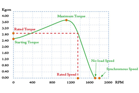
Rated Torque
The torque at rated rpm is the rated torque.
NO-LOAD RPM
Motor rpm without load.
Continuous Rating and Short-Period Rating
Continuous rating refers to continuous operation of the motor under rated output; shhort-period rating refers to motor running at rated output within a specified period of time.
Output Power
- Indicated the power that can be performed by a motor within a unit time. The power performed by the motor is determined by rpm and torque. Reference formula is as below:
- Output (Kw) = ( T x N ) / 97400
- T:Torque (Kgcm)
- N:RPM
- 1HP:0.746Kw
Starting Torque
The torque is produced instantly when motor is started. The motor will not start in case a load is larger than such a torque.
Slip
- One of the methods to indicate rpm, reference formula as below:
- S = ( Ns - N ) / Ns
- S:Slip
- Ns:Synchronous rpm
- N:RPM undeer any load
SELECTION OF MOTOR
General Introduction of Speed Reducer Series Calcuation of Reduction Gear Ratio
Customers choose the most appropriate reduction gear ratio according to their requirement to match output rpm of gear reducer with the rpm of operating machines. (AAC)
- i = Nm / Ng or 1 / i = Ng / Nm
- i:Gear ratio
- Ng:Output Speed of gear reducer (rpm)
- Nm:Motor running speed (rpm)
Torque Calculation Formula of Direct Link Speed Reducer
Customer choosed the most appropriate model to suit the machine's output torque of the speed reducer. (Constant torque)
- Tg = Tm x i x η
- Tg:Reducer output torque
- Tm:Motor output torque
- i:Ratio
- η:Speed reducer transmission efficiency
Maximum Permissible Torque
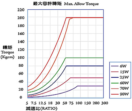
Output torque of speed reducer is calculated according to the formula described above. When reduction ratio is larger, its withstanding load torque is limited, due to restrictions of the gearbox quality and the structural design of the speed recuder itself. Therefore, all models have the restriction of their maximum permissible torque. (See diagram below.)
BASIC CALCULATION OF MOTOR CAPACITY
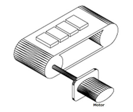
Maximum Permissible Torque
- Pg = (P1 + P2 + P3) x 100 / η [W]
- P1 = 9.8 x μ x W x V x λ [W]
- P2 = (μ x Q x λ) / 367 [W]
- P3 = ± (Q x H) / 367 [W]
- λ:Length of conveyor (distance between shafts) (m)
- W:Weight of unit length of belt (kg/m)
- μ:Friction coefficient
- V:Belt speed (m/sec)
- Q:Conveyance volume (kg/h)
- η:Efficiency (%)
- H:Difference in height between two ends of conveyor (m)
Field of Lifting Up the Loading
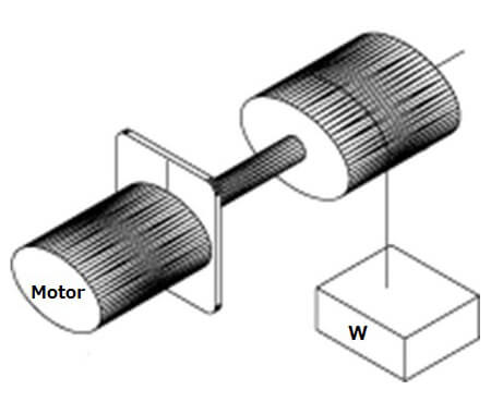
Pg = (W x V) / (6 x 12) x (100/η) [W]
Field of Driving Inertia Body
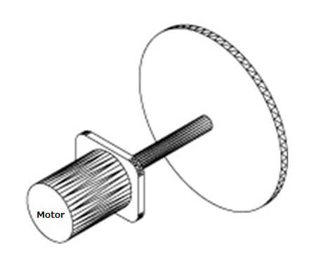
- Pg = 1.027 NT [W]
- T ≒ (GD² /375) x (N/t) [kgf x m]
- N:Revolutions per minute (rpm)
- T:Torque (kgf x m)
- GD²:Flywheel effect (kgf x m2) (including flywheel effect of rotor)
- t:Starting time (sec)
Field of Level Movement On Contact Surface
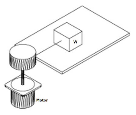
Pg = (μ x W x V) / (6 x 12) [W]


